Table of Contents
Toggle1.Brief introduction to LSR molding molds
In general, the structure of injection molding molds for solid liquid silicone rubber (LSR) is similar to that of molds used for thermoplastic materials, but there are also many significant differences. For example, LSR compounds generally have a low viscosity, so the mold filling time is very short, even at very low injection pressures. In order to avoid air entrapment, it is crucial to have good exhaust devices in the mold.
In addition, LSR compounds do not shrink in the mold like thermoplastic materials. They tend to expand when heated and slightly contract when cooled. Therefore, their products do not always stay on the convex surface of the mold as expected, but are retained in the mold cavity with a larger surface area.
2.Key elements in LSR molding mold design
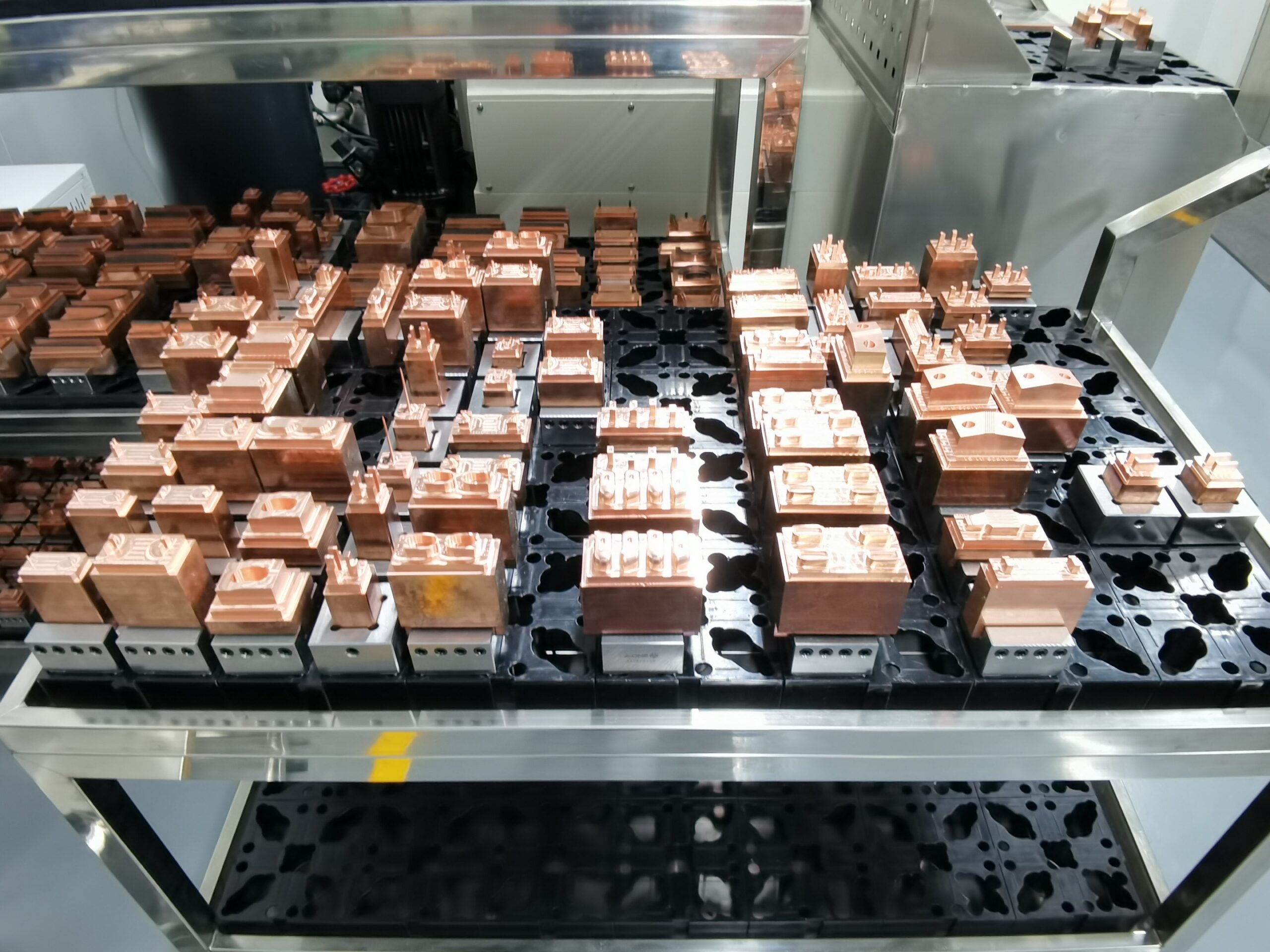
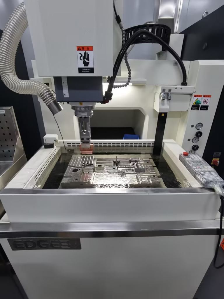
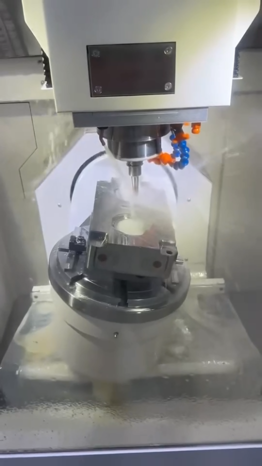
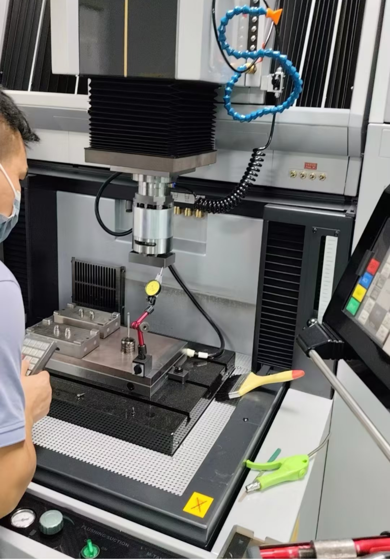
(1) Precision machining: Liquid silicone is a material with extremely good fluidity. If there is a gap larger than 0.002, the glue will enter. Therefore, the requirements for precision are extremely high. This requires high-precision processing equipment and high-precision mold inspection equipment. This is the necessary and most basic requirement.
(2) Temperature control: Temperature has a significant impact on the fluidity and curing speed of liquid silicone. Therefore, the control of temperature must be very precise. When designing a mold, the design of the heating system and the design of the heat transfer runner are very important. According to different materials and structures, different heating elements should be selected, such as heating by heating tubes or oil heating. How to control the temperature difference for the conduction of temperature in different metal media? These are all technical difficulties.
(3) Runner design: The low viscosity and rapid curing characteristics of liquid silicone require proper runner design of the mold to ensure that the material can fill the mold evenly and quickly and avoid bubbles and defects. The runner design should take into account pressure distribution and flow balance to ensure simultaneous curing of all parts.
(4) Exhaust system: Since liquid silicone will generate gas during the curing process, the mold design needs to have effective exhaust channels to prevent the formation of bubbles and affect product quality. Moreover, the design and processing control of the runner should be based on different requirements of product requirements and efficiency to design different runner modes, such as cold runner (open type, needle valve type), semi-cold runner, ordinary runner, and so on.
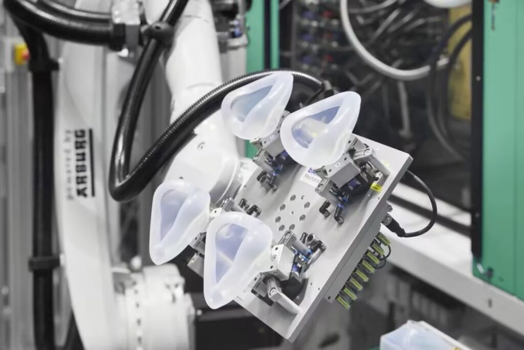
(5) Demolding design: Liquid silicone products have a smooth surface and viscoelasticity. When designing a mold, demolding angles and appropriate demolding mechanisms should be considered. Whether it is air ejection, automatic mechanical hand clamping, ejection or blowing, to ensure that the product is easily demolded without damage and ensure the highest efficiency.
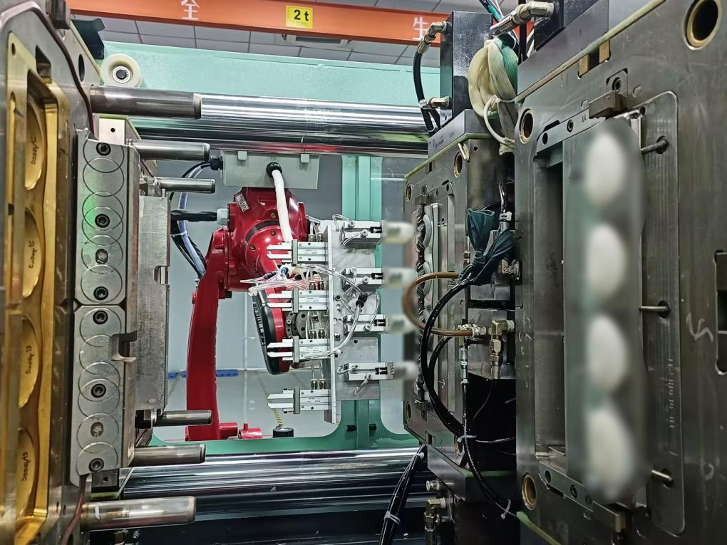
(6) Structural design: Liquid silicone molds usually adopt two-plate mold design. Sometimes, three-plate or multi-plate molds may be used for more complex designs to meet the structural needs of products. When products have complex structures such as deep cavities, thin walls, undercuts, and fine textures, the design and manufacturing of molds face huge challenges. The design of the cavity should perfectly fit these complex shapes, and the layout of the runner should ensure that the liquid silicone is fully and evenly filled into every corner.
(7)Material selection: Mold materials need to have high hardness, high wear resistance, corrosion resistance, and good thermal conductivity to ensure that the mold will not wear out too quickly during long-term use. In addition, factors such as the processing performance and cost of materials need to be considered. Select appropriate mold materials under the premise of meeting performance requirements.
3.Design difficulties and countermeasures of LSR molding molds
(1) Shrinkage rate
Although LSR does not shrink in the mold, after demolding and cooling, they often shrink by 2.5%-3%. To a certain extent, the exact amount of shrinkage depends on the formulation of the compound. However, from the mold perspective, the shrinkage rate may be affected by several factors, including the temperature of the mold, the temperature of the compound when demolded, and the pressure in the mold cavity and the subsequent compression of the compound.
The location of the injection point is also worthy of consideration, because the shrinkage rate in the direction of compound flow is usually larger than that in the direction perpendicular to the compound flow. The external dimensions of the product also affect its shrinkage rate. Generally, the shrinkage rate of thicker products is smaller than that of thinner ones. If secondary vulcanization is required, an additional shrinkage of 0.5%-0.7% may occur.
(2) Parting line design
Determining the location of the parting line is one of the first steps in designing an LSR injection molding mold. Exhaust is mainly achieved through grooves located on the parting line. Such grooves must be located in the area where the injection compound reaches last. This helps to avoid internal bubbles and reduce strength loss at the adhesive joint.
Due to the low viscosity of LSR, the parting line must be precise to avoid glue overflow. Even so, parting lines can often still be seen on the finalized products. Demolding is affected by the geometric dimensions of the product and the location of the parting surface. Designing the product with a slight chamfer helps to ensure that the product has a consistent affinity for the required other half of the mold cavity.
(3) Exhaust device
As LSR is injected, the air remaining in the mold cavity is compressed when the mold is closed and then discharged through the ventilation grooves during the filling process. If the air cannot be completely discharged, it will remain in the compound (this often causes the product to partially show a white edge). The ventilation grooves generally have a width of 1mm – 3mm and a depth of 0.004mm – 0.005mm.
Applying a vacuum in the mold can create the best exhaust effect. This is achieved by designing a gasket on the parting line and quickly evacuating all the mold cavities with a vacuum pump. Once the vacuum reaches a rated level, the mold is completely closed and injection molding begins.
Some injection molding equipment allows operation under variable closing forces, which enables processors to close the mold at low pressure until 90% – 95% of the mold cavity is filled with LSR (making it easier for air to be discharged), and then switch to a higher closing force to prevent glue overflow due to the expansion of liquid silicone.
(4) Injection point design
A cold runner system is used when molding LSR. This can maximize the advantages of this compound and increase production efficiency to the maximum. Processing products in this way eliminates the need to remove the injection runner, thus avoiding increasing the labor intensity of operations and sometimes avoiding a large amount of material waste. In many cases, the runnerless structure can also shorten the operation time.
The rubber injection nozzle is controlled by a needle valve for forward flow. At present, many manufacturers can provide injection nozzles with pneumatic switches as standard equipment and can install them at various parts in the mold. Some mold manufacturers have specially developed an open cold runner system with a very small volume, so that multiple injection points can be set up in an extremely limited mold space (and then fill the entire mold cavity). This technology makes it possible to mass-produce high-quality liquid silicone products without separating the rubber injection port.
If a cold runner system is used, it is important to form an effective temperature separation between the hot mold cavity and the cold runner. If the runner is too hot, the compound may start to vulcanize before injection. But if it cools too quickly, it will absorb too much heat from the gate area of the mold, resulting in incomplete vulcanization.
For products injected with conventional runners (such as submarine runners and conical runners), it is advisable to use a small-diameter injection gate for feeding (the diameter of the feeding gate is usually 0.2mm – 0.5mm). Low-viscosity LSR compounds, like thermoplastic compounds, require a balanced runner system. Only in this way can all the mold cavities be evenly filled with compound. The use of simulation software for designing runner systems can greatly simplify the mold development process and prove its effectiveness through filling tests.
(5) Demolding design
Vulcanized liquid liquid silicone easily adheres to the surface of metal, and the flexibility of the product makes demolding difficult. However, LSR’s high-temperature tear strength enables it to be demolded under normal conditions, and even large products will not be damaged. The most common demolding techniques include stripper plate demolding, ejector pin demolding, and pneumatic demolding. Other common techniques include roller scraping demolding, ejection plate demolding, and automatic demolding.
When using a demolding system, it must be kept within a high-precision range. If the gap between the ejector pin and the guide pin bushing is too large, or if the gap between components becomes larger due to long-term wear, glue overflow may occur. Inverted conical or mushroom-shaped ejector pins are very effective because they allow for greater contact pressure and facilitate improved sealing.
(6) Mold material selection
Mold pallets are commonly made of non-alloy tool steel (no. 1.1730, DIN code C45W). For mold pallets that need to withstand high temperatures of 170℃ – 210℃, considering impact resistance, pre-tempered steel (no. 1.2312, DIN code 40 CrMn-MoS86) should be used. For mold pallets with mold cavities, tool steel that has been nitrided or tempered should be used to ensure its high-temperature resistance.
For LSR with high filling capacity, such as oil-resistant grade LSR, materials with higher hardness are recommended for manufacturing molds, such as bright chrome-plated steel or powder metal (no. 1.2379, DIN code X155CrVMo121) specially developed for this purpose. When designing molds for highly wear-resistant materials, those components that withstand high friction should be designed as replaceable forms, so that the entire mold does not need to be replaced.
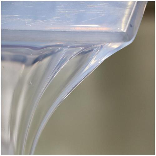
The inner surface of the mold cavity has a great influence on the smoothness of the product. Most obviously, the finalized product will completely match the surface of the mold cavity. Molds for transparent products should be made of polished steel. Titanium/nickel steel after surface treatment has extremely high wear resistance, while polytetrafluoroethylene (PTFE)/nickel makes demolding easier.
(7) Temperature control
Generally speaking, electric heating is suitable for LSR molding. Usually, strip heaters, tubular heaters or heating plates are used for heating. The key is to make the temperature field of the entire mold evenly distributed to promote the uniform curing of LSR. On large molds, oil temperature control heating is an economically effective heating method.
Covering the mold with insulation boards is beneficial to reducing heat loss. Inappropriate conditions at any part of the hot mold may cause large temperature fluctuations between operating procedures or cause air leakage. If the surface temperature drops too low, the curing speed of the compound will slow down, which often makes it impossible to demold the product and causes quality problems. A certain distance must be maintained between the heater and the parting line to prevent the template from warping and deforming and forming glue overflow burrs on the finished product.
For molds designed with cold runner systems, complete separation between the hot end and the cold end must be ensured. Special titanium alloys (such as 3.7165 [TiA16V4]) can be used for manufacturing. This is because its thermal conductivity is much lower than that of other steels. For an overall mold heating system, insulation boards should be placed between the mold and the mold pallet to minimize heat loss.
Proper design and conception can ensure LSR injection molding. In this regard, the mold is very important. The above mold design principles aim to fill the mold cavity with compound, shorten the curing time, produce high-quality finished products with high output, so that liquid silicone processors can obtain good economic benefits.
As a high-tech enterprise with more than 20 years of design and manufacturing of liquid silicone molds, Jutai has a technical team with strong technical strength and rich experience, and has strong precision mold design and manufacturing capabilities. Jutai will provide product design review services for customers. Jutai’s professional engineer team analyzes the mold flow and design scheme to ensure that the precision of the mold is accurate to less than 0.003mm, and strictly controls the front-end review and processing progress inspection. It also has a professional in-house tooling production workshop, which ensures the accurate transmission and reception of design ideas, and strives to do it right the first time and reduce the R & D trial and error cost for customers. Under the condition of meeting customers’ innovative thinking, it achieves the goal of being scientific, efficient and cost-effective!